Carve Out Pockets with Your CNC


One of the most used toolpaths in CNC woodworking, the pocket toolpath works for many applications, such as carving recesses for inlays and trays, mortises and other joinery, and more. Once you understand the basic concepts, the door to creatively using pocket cuts swings wide open.
In this article, I use Vectric VCarve software (vectric.com) to illustrate setting up and using a pocket toolpath. All CNC software packages have a pocket toolpath, although it may go by a different name.
The basics

The primary function of a pocket toolpath is carving out the inside area of a design, such as the square or hand shown in photo, above. The shape must be a continuous line, or a closed vector as it's referred to in VCarve. Selecting this line allows you to use the Pocket Toolpath panel (photo, below) to assign a bit to rout out this area, and control how that bit moves and cuts.


When you first look at the Pocket Toolpath panel, the many settings may seem overwhelming. You may not use all of them, but focusing on the primary ones will increase your CNC capabilities.
How deep will you go?

Starting at the top of the Pocket Toolpath panel, you find the Cutting Depths setting (photo, above.) These settings often confound new CNC users, because they are additive. The Start Depth represents where the bit starts cutting, and generally this setting is left at zero, so the bit starts cutting on the top surface of your board. The Cut Depth represents the amount of material to be removed. If you already have a pocket cut on your project (for example, the square in photo, above) and want to cut a deeper pocket (the hand) inside the first, set the Start Depth to begin cutting at the bottom of the first pocket and the Cut Depth to the amount of additional material to remove. This saves time because you don't "cut air" when beginning the second pocket cut.
Pick a bit and set its options
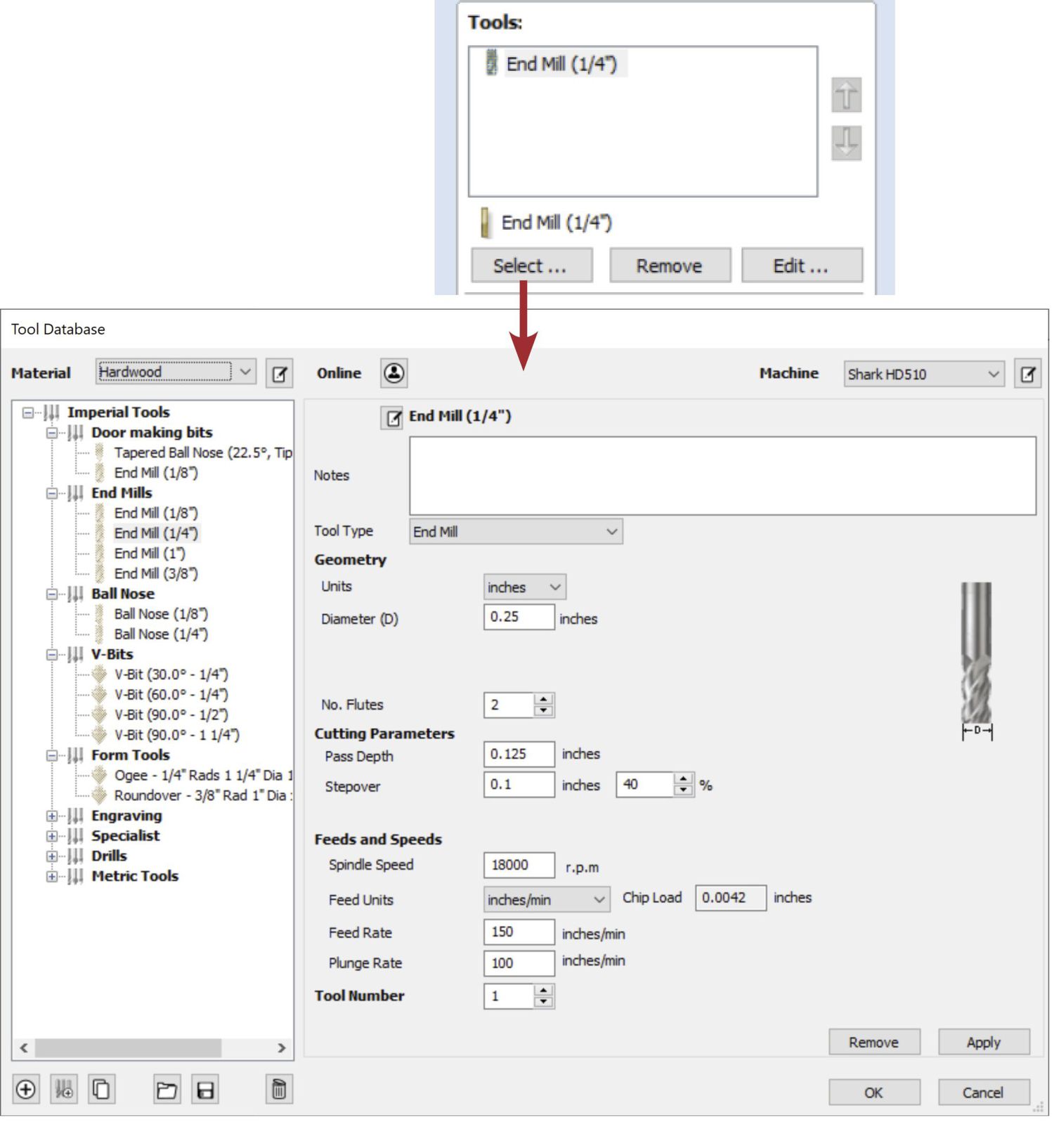
Moving down the panel, find Tools. In this section, select and configure the router bit(s) you want to use with the pocket toolpath. Clicking on the Select… button opens the Tool Database (photo, above.) From this list, select the bit(s). If you choose two or more bits, the toolpath uses the largest bit to clear out most of the material, and the smaller bit cleans up the details (photo, below.)

Get your pass and directions

The Passes section of the panel defines the number of passes it takes to reach the bottom of the pocket (photo, above.) Fewer, deeper passes reduce cutting time but increase the strain on the bit. In this section, you can also add a shallow final pass to improve the cut quality at the bottom. For starting out, I recommend using the defaults and running a few tests before changing the settings here.


Below the Passes setting, you can specify an Offset or Raster method for cutting the pocket (photos, above.) Using the Ramp Plunge Moves setting reduces pressure on your bit and machine, improving the cut quality at the point of entry (photo, below.)

Save your allowance

The Pocket Allowance provides a way to overcut or undercut the sides of the pocket, a useful feature when you make parts that must fit together, such as a half-lap joint (photo, above.) Because a good CNC cuts parts precisely, adding some pocket allowance prevents parts from fitting too tightly. I also find it useful when the pocket must accommodate a part cut on a different machine, such as a tablesaw, because the part from the tablesaw may be slightly over- or undersized, or may have changed size due to shifts in humidity. This setting is also helpful for dowels that vary in size.
Using the pocket allowance gives you a quick way to adjust the size of the hole, so the dowel fits perfectly. Below the Pocket Allowance option is a check box for Use Vector Selection Order. Use this option when you have multiple pockets and want to cut them in a specific order.
Specialty pocket options
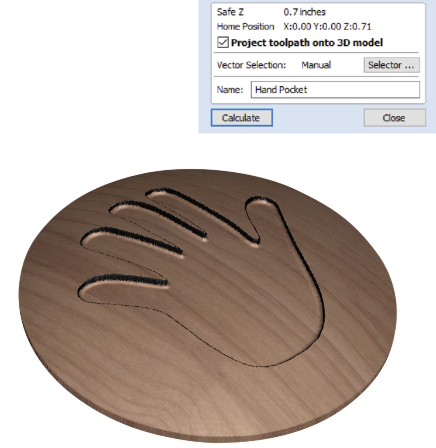
Find a couple of advanced settings at the bottom of the Pocket Toolpath panel. First, Project toolpath onto 3D model does just what it says (photo, above.) The next one, Vector Selection, allows you to select a particular vector type from your design. For example, if your design includes a variety of circles, use this option to select and associate all the circles of a specific size for this toolpath. It proves useful with complex designs or in production situations.
A few more tricks

Although it is common to use a straight bit with the pocket toolpath, you can also use other types. For example, combine a bowl bit with the pocket toolpath to create shallow bowls and trays (photo, above and opening photo.)


The pocket toolpath can also make finger and mortise-and-tenon joints. Because a router bit leaves rounded corners, VCarve provides two methods to allow the parts to fit together (photo, above.) Although using a profile toolpath, which cuts only the perimeter of the opening, is sometimes quicker, it leaves a small chunk of wood in its center that can jam the bit or damage the joint. I prefer using the pocket toolpath because it routs away all the material inside the mortise or finger opening.