Improve job security with two vises


Either of these vises will ease your woodworking life; adding both will change your life.
The twin-screw vise [Sources, end of story] accommodates wide or long pieces between the screws for slip-free holding: just the ticket when hand-cutting dovetails. The long jaws steady a board for edge jointing with a hand plane, and bench-dog holes at each end align with rows on the benchtop.
The leg vise features a deeper throat (distance from the top of the bench to the vise screw) and a larger jaw opening than just about any other vise. Leverage provided by the long jaw means more clamping pressure. With most parts made of wood, you'll buy only the screw assembly, saving dough.
Manufacturer's instructions included with the vises cover installation for different workbench configurations. But workbenches are as unique as the woodworkers who use them, so you may need to adapt the technique and dimensions to suit your own bench. Read the manufacturer's instructions for part identification and details concerning adjustment and troubleshooting.
Note that in our installation the workbench end skirt acts as the rear jaw for the twin-screw vise, eliminating the need for the rear-jaw mounting hardware and steel dowel pins listed on the Vise Components drawing in the manufacturer's instructions.
Twin-screw end vise
Make the jaw
Tip!
To prevent binding and ensure smooth vise-screw operation, check the perpendicular alignment of the drill press table and drill bit before drilling any parts.
1.
Laminate an oversize blank for the front jaw (A) [Materials List, end of story, End-Vise Exploded View, below] and cut it to size. On the drill press, drill the vise-screw holes and bench-dog counterbores and holes [Drawing 1, below]. Shape the bottom corners and chamfer the front edges.


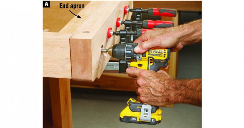
2. Clamp the front jaw to the workbench end skirt, flush at the top and ends, capturing scrap backer blocks on the inside face of the skirt. Drill vise-screw holes through the skirt [Photo A, below]. Remove the clamps, front jaw, and backers.
3. Remove the benchtop from the base and position the top upside down. Cut the vise-nut blocks (B) [Exploded View, above] and clamp them into the corners where the short blocking meets the end skirt. Using the 11⁄2 " bit and the vise-screw holes in the skirt as guides, mark hole centers on the vise-nut blocks. Mark the blocks for re-installation, remove them, and drill the 2" holes at the drill press.
4. Insert the vise nuts into the block holes, drill pilot holes, and fasten the nuts with the provided #14×11⁄2 " screws. Install the blocks [Photo B, below].

5. Drill 11⁄2 " holes where the vise screws pass through the legs [Exploded View, above, Photo C, below]. Reinstall the benchtop on the base.

6. Form a 2° taper on the inside face of the front jaw by double-face-taping a spline to the jaw [Drawing 2, below] and running the jaw spline-side-down through a surface planer.

Add the hardware
Note:
Slightly tapering the front jaw (A) ensures equal holding power across the width of the jaw under full clamping pressure.
1. Remove the rust-inhibiting wax coating from the vise screws with mineral spirits and an old toothbrush. With the chain wrapped around the sprockets and the spring-loaded pin engaged in the right-hand sprocket, slide the front jaw onto the vise screws. Then, thread the vise screws into the vise nuts in the benchtop, keeping the front jaw parallel to the benchtop skirt. Tighten the screws enough to hold the jaw in place. Align the jaw ends and top edge with the end of the benchtop and orient the vise-screw thrust plates vertically [Drawing 3, below]. Using the thrust-plate holes as guides, drill pilot holes and secure the plates with the provided lag bolts and washers. Do not overtighten.
Note:
We installed the driving screw with the spring-loaded pin on the right and the follower screw on the left. You may reverse this orientation if you wish.
2. Make sure the spring pin engages the right-hand sprocket and "zero" or permanently align the vise jaws [Drawing 3].

Note:
To accommodate the vise screw center-to-center distance for this installation, shorten the supplied chain to 62 links, following the manufacturer's instructions.
3. Cut the main cover to length [Drawing 4, above] and insert it between the end caps with its ends under the end-cap flanges. Mark the mounting holes onto the front jaw. Remove the cover, drill pilot holes, and install the cover with the provided screws.
4. Assemble and install the vise handles, following the manufacturer's instructions. Lubricate the screws with grease. Wipe any excess off the thread crown, leaving grease only in the thread grooves.
Leg vise

Form the vise jaw
Note:
Check the length of your guide bushing before making the templates. Ours allowed using 1⁄2" plywood; some may require 3⁄4" plywood.
1. Laminate an oversize blank for the jaw (C) and cut it to size [Materials List, at end of article]. Lay out the mortise and its horizontal centerline [Drawing 5, below]. Then lay out the main-screw hole and a larger concentric circle for aligning the main-screw flange.

2. At the drill press, drill the main-screw hole and pilot holes for trim-head screws that secure the pin board in the mortise.
3. Make Template 1 [Drawing 6, below] from 1⁄2 " plywood, edge-joining the parts. Install a 3⁄4 " guide bushing and 1⁄2 " up-cut spiral bit in a plunge router. Clamp the template to the inside jaw face, edges flush and horizontal centerlines aligned, and rout the mortise.

4. Bandsaw and sand the radius at the top of the jaw [Drawing 5, above]. Lay out the side tapers and bandsaw and joint the jaw to final shape. Chamfer the edges.

5 Cut the pin board (D) to shape [Drawing 7, above] and drill the holes at the drill press. Round-over the edges. Clamp the pin board into the jaw mortise [Leg-Vise Exploded View, below], and drive the trim-head screws. (Download full-size pin-board and pin-handle patterns.)
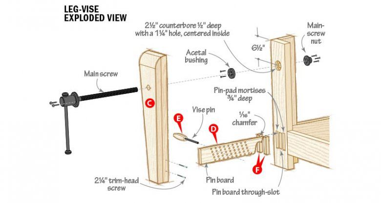
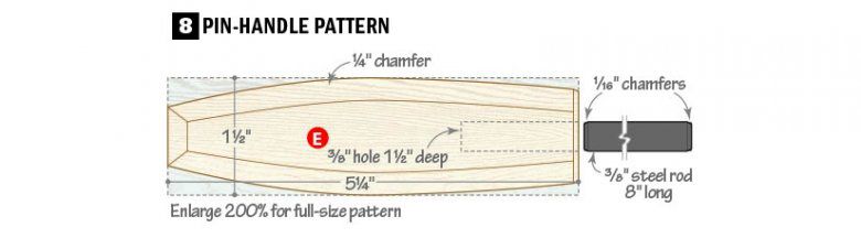
6 Cut the pin handle (E) [Drawing 8, below] and drill the hole. Make two copies of the pattern, apply them to adjoining faces, and form the handle profile. File and sand the chamfers. Cut a steel rod to length, grind or file chamfers on the ends, and epoxy the rod into the handle.
7. Place the jaw horizontally on sawhorses and slide the main screw into the hole. Center the screw flange in the circle drawn on the jaw. Using the holes in the flange as guides, drill pilot holes and drive the supplied screws. Set the jaw assembly aside.
Modify the bench leg
Note:
Your plunge router acts as a portable drill press, keeping the holes in the leg perpendicular to the surface.
1. Make Templates 2–5 [Drawing 6, above]. Drill the holes in Templates 2 and 3 with Forstner bits or holesaws at the drill press. Mark horizontal centerlines on both faces of Template 4 and one face of Template 5.
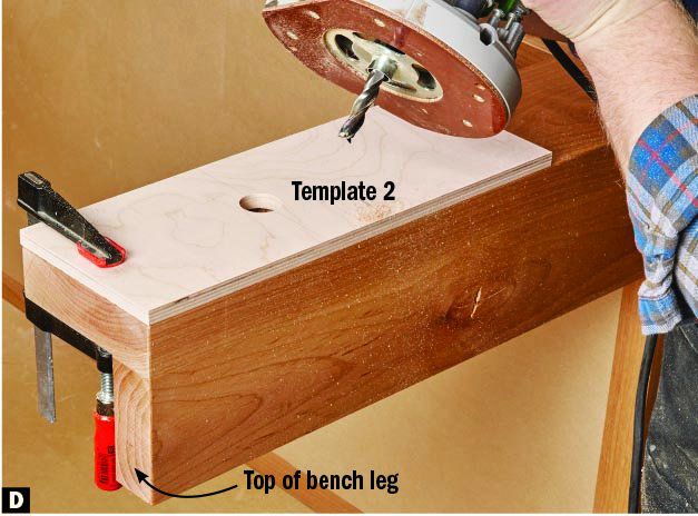
2. Remove the benchtop from the base and position the base on its side. Form the main-screw hole and counterbore in the bench leg [Leg-Vise Exploded View, above, Photos D and E, below] with the same guide bushing and bit used for the jaw mortise.

3. Rout the pin-pad mortises [Photos F and G, below] and the pin-board through-slot [Photo H, following]. Square the corners of the pin-pad mortise with a chisel.


4. Cut and chamfer the pin pads [Photo F, above], and glue them into the leg mortises.
5. Apply Danish oil to the jaw, pin board, pin handle, pin pads, jaw hole and counterbore, and pin-board slot.
Assemble the vise
Tip!
For replaceable, no-mar work holding, double-face tape leather to the mating jaw faces.
1. Wipe the rust-preventative oil off the vise parts. Follow the manufacturer's instructions for assembling the hub, main screw, and flange.
2. Position the acetal bushing in the bench-leg counterbore, orienting the elongated opening vertically. Drill pilot holes and fasten the bushing with the included screws. Note the positions of the screws [Leg-Vise Exploded View, above].
3. Mount the jaw assembly, sliding the pin board into its slot as you slide the main screw through the acetal bushing. Thread the main-screw nut onto the screw, snugging it against the inside of the bench leg. Move the nut and screw up and down to find the extents of the bushing opening and center the screw vertically in the bushing. Tighten the main screw, making sure the holes in the nut do not align with the bushing screws. Drill pilot holes and fasten the nut with the included screws.
4 Back off the main screw, opening the jaws. Re-install the benchtop on the base. To use the vise, position the vise pin in the pin-board so the top edge of the jaw grips the workpiece as the jaw slightly tips out at the bottom.
