Make Your Own Cove Molding

Creating Your Own Molding
Off-the-shelf cove molding from the home center is convenient, but it limits your choices in widths, profiles, and wood species. For custom molding that perfectly matches your project, create your own. Best of all, you don't need fancy machines--just your tablesaw.
The photo at above shows the secret to doing this: Feeding stock at an angle across the blade cuts a concave profile. Using this procedure, we created a cove molding as shown below. With some experimentation, you can create a wide variety of cove profiles [Cove creativity, last slide] for your projects or maybe to trim a room.

Blade Selection
To minimize scoring and reduce sanding, install a 60- or 80-tooth crosscut blade in your tablesaw. You'll also need two scrapwood fences to place diagonally across the saw table, capturing the blank while you cut it, as shown above. Joint one edge of each fence square to a face.
For the 33⁄8 "-wide molding used on the hall bench, prepare blanks 41⁄2 " wide with parallel edges. The extra width allows for bevel-rips made after cutting the cove [Drawing 1].
Quick Tip! Better long than short. Make more molding than you need. It's easier to make extra now than to try to duplicate a setup later.

Build a Jig
A simple fence-setting jig [Drawing 2] determines the proper angle for the fences on the tablesaw. Build the jig as shown, ensuring that opposing sides are parallel.
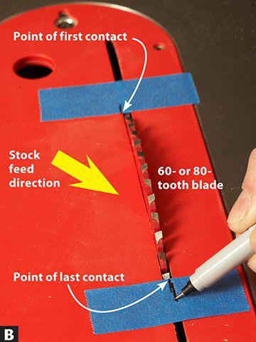
Set the distance between the jig's long arms to the width of the cove and tighten the wing nuts to lock the jig in shape. Raise the tablesaw blade to the final depth of the cove (1⁄2 " for our example), and use painter's tape to mark where the teeth enter and exit the throat plate [Photo B]. Lower the blade and use the marks to position the jig [Photo C].
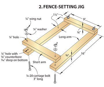


After marking one inside edge of the jig onto the tablesaw top using a pencil as shown, remove the painter's tape and clamp the fences in place [Photos D, E].


Molding the Cove
Form the cove by making a series of passes over the blade. To start, set the blade height 1⁄13 " above the table. Turn the saw on and use push blocks to slowly feed the molding blank over the blade, top photo. Raise the blade 1⁄16 " and make another pass. Repeat this procedure until you reach the final cove depth.
Quick Tip! Lighten up and be smooth. A slow final pass removing 1⁄32 " or less leaves a surface that requires less sanding.
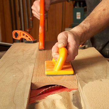
Using the newly cut molding as a template, trace the profile of the cove onto the end of a piece of foam insulation and cut it to rough shape at the bandsaw or with a coping saw. Sand the block to final shape [Photo F]; then sand the cove starting at 100 grit and working up to 220 grit.

Lay out the molding profile on one end of each cove blank [Drawing 1] and bevel-rip the edges to complete the molding [Drawing 3].
Safety Note: Use a zero-clearance insert to prevent the waste from catching between the throat plate and the blade.

Watch these methods demonstrated in this free video.
Creating Cove Profiles
Three variables determine the profile of cove molding shaped on the tablesaw: the feed angle of the stock over the blade; the blade height; and the blade tilt angle. Different combinations of these three elements create a variety of profiles. (See the drawings.)

A shallow feed angle cuts a compact, elliptical cove [top drawing]. Higher feed angles broaden the curve to a near semi-circular profile.
Final blade height determines the depth of the cove. To see the cove depth cut by a 3⁄8 "-high blade, for example, cover the top drawing just below the 3⁄8 " line (shaded area). The depth of the profile shows above the line (unshaded area).
A blade set 90° to the table cuts a symmetrical cove [top drawing]. Tilting the blade creates asymmetrical coves that "lean" to one side [bottom drawing].
Safety Note: When tilting the blade, feed the stock from the direction the blade tilts. So if your blade tilts to the left, feed the stock from left to right. If it tilts to the right, feed right-to-left.
Experiment to find profiles you like. Save short lengths of your samples and write the feed and blade tilt angles on them for future reference.
©Copyright Meredith Corporation 2002, 2010