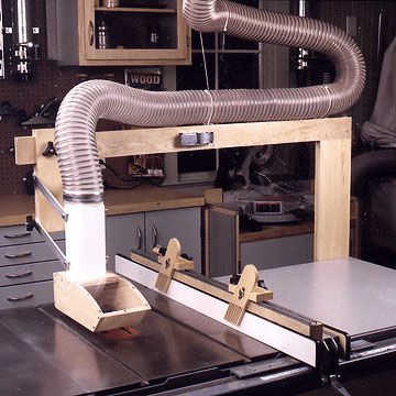
Tablesaw Dust Collector

Safety Warning
Safety Warning: Do not remove a factory-installed blade guard to install this accessory. We've designed this dust-collector hood for those who do not have the blade guard provided by the saw's manufacturer. You must use feather boards in conjunction with this hood; we show you how to build those on page 14 in the Downloadable Plans. In use, adjust the height of the hood over the saw table to suit the thickness of the stock you're sawing, and tighten the wing knobs. We like to set the height to the thickness of the material plus 1⁄4 ".
Measure First
Measure before you begin
Before you begin construction, take a few measurements so you can fit the accessory to your tablesaw. Refer to the Exploded View and Tablesaw Extension Mounting drawings.
1 To determine the length of the support arm (H), measure from the right end of your saw's table extension to the center of the blade. Add 51⁄2 ", and divide the total by 2. Round the result to the nearest 1⁄8 ". This dimension will be the length of each part H.
2 Install a spacer or spacers on the underside of your saw's table extension, if necessary, to provide an attachment surface for the mounting bracket (J). If your fence has a back rail, locate I and J to clear it.
The rabbeted top end of the upright (I) needs to stand 171⁄2 " above the saw table's surface, so measure from the bottom surface of the spacer (which will be the top of part J) to the top surface of the table. This distance plus 171⁄2 " equals the length of part I.


Build the Hood
Build the hood body first
1 Cut two pieces of stock for the Hood Sides (A) to the dimensions shown in the Bill of Materials found in the Downloadable plans at the end of this story. Temporarily fasten them together face to face, aligning the edges. (We did this with double-faced tape.)
2 Photocopy the full-size pattern for the hood side, found on pages 12 and 13, in the Downloadable Plans at the end of this story. Adhere the pattern to the stacked blanks.
3 Bandsaw slightly outside the pattern line; then sand the parts to shape. Drill six 9⁄64 " holes and a 3⁄16 " one where indicated. Separate the parts, and remove the pattern.
4 Cut the hood top (B) to size. Mark the center for the 43⁄16 " hole, where shown on the Parts View drawing on page 9, of Downloadable Plan. Using a circle cutter and drill press, bore the hole, sized for 4" PVC sewer and drain (S&D) pipe. (This pipe, available from home centers, is smaller than 4" Schedule 40 PVC pipe.)
5 Saw or rout a 3⁄4 " rabbet 1⁄8 " deep on the top of part B where shown. Then saw the front end to a 45° bevel.
6 Cut the front (C) to size. Saw, sand, or plane bevels on the top and bottom edges where shown on the Hood drawing.
7 Cut the hood back (D) to size. Bevel the bottom edge.
8 Clamp parts A, B, C, and D together. Then, guiding through the holes in the sides (A), drill pilot holes for #6x11⁄4 " flathead wood screws. Drill and countersink the 3⁄16 " hole through the back (D), and countersink the screw holes in the sides (A). Unclamp the hood body assembly, apply woodworker's glue to the joints, and drive in the wood screws.


Build the Bracket
Build the adjustable bracket
1 Cut the bracket panel (E) to size.
2 Form a 3⁄8 " slot where shown. To do this easily, install a fence on your table-mounted router and set stops on it, as shown in the Routing the Bracket Slot drawing.
3 Cut the cleat (F) to size. Glue it to the face at the top end of the panel (E), as shown in the Bracket drawing.
4 Laminate stock for the bracket body (G), support arm (H), upright (I), and mounting base (J). (We laminated 3⁄4 "-thick birch, and planed it to 11⁄4 " thick, taking equal amounts from each side.) Cut parts G, H, I, and J to size.
5 Mark centers on one edge of the bracket body (G) where shown. Using a drill press for accuracy, drill a 25⁄64 " hole at each mark.
6 Complete the sliding bracket by gluing the bracket body (G) to the panel (E) where shown. Position one section of the support arm (H) between the body (G) and the cleat (F) as a spacer. (To provide clearance for smooth sliding, stick a strip of masking tape to each edge of the support arm as temporary shims.) Remove the support arm before the glue dries.

Add the Support
Now, for a supporting structure
1 Drill two 1⁄2 " holes through the support arm (H), centered on the edge near one end. The Support drawing shows their locations. Use a drill press for accuracy.
2 Drill a 3⁄8 " hole near the end of the other half of the support arm, where shown on the Exploded View drawing. Verify the hole's distance from the bottom of the arm (H) by placing the bracket assembly on the arm. The slot and the hole must coincide.
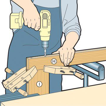
3 Bore 1⁄2 " bolt holes into the ends of the upright (I), where shown on the Parts View drawing on page 10 in the Downloadable Plans. The holes in the top must mate exactly with those in the support arm (H), as shown in the Support drawing, top drawing.
To locate and drill the holes accurately, clamp the drilled arm to the upright, as shown in the center illustration. With a 1⁄2 " bit chucked in a portable drill, guide through the holes in the arm to start the holes in the upright. Drill as deep as you can with the arm in place. Then remove the arm, and drill the holes to the depth specified, as shown in the bottom illustration. Drill both ends of part I this way.
4 Bore 11⁄2 " holes in the face of the upright to intersect the bolt holes, shown on the Parts View drawing in the Downloadable Plans. A Forstner bit and drill press will do the job easily.
5 Rout a stopped groove in the underside of the support arm (H), at the end with the 1⁄2 " holes, as dimensioned on the Support drawing.
Make the cut with a 1⁄2 " straight bit chucked in a table-mounted router. Position a fence to center the bit on the edge of the arm (H), and clamp a stopblock to it to stop the cut 51⁄2 " from the end. Cut the groove in several progressively deeper passes.
6 Form a tenon on one end of the upright (I) to mate with the groove in the arm. To do that, saw or rout 3⁄8 " rabbets 1⁄2 " deep on the end, as shown in the Support drawing, above.
7 Finish-sand the wooden parts and assemblies. Mask the groove in the arm (H) and the tenon on the upright (I); then apply a clear finish. (We applied two coats of Aqua ZAR water-base polyurethane, sanding between coats with 220-grit sandpaper.)

Attach to Saw
Attach the support to your saw
1 Cut the mounting base (J) to size. Using the drilled support arm as a template, drill two 1⁄2 " bolt holes through one end where shown. Drill appropriate screw holes in the part, and attach it to the spacer under the saw table extension.
2 Bolt the upright to the mounting base with two 1⁄2 x5" hex-head bolts and nuts, as shown.
3 Join the two support arm halves (H) with a heavy-duty hinge on the back, as shown in the Exploded View drawing. Install a heavy-duty draw catch on the front.
4 Attach the assembled arm to the upright with two 1⁄2 x8" hex-head bolts, as shown in the Support drawing. Slide the bracket assembly (E/F/G) onto the arm, and install a 3⁄8 x21⁄2 " carriage bolt, washer, and knob or wing nut, as shown in the Exploded View drawing.
Add the Plastic Parts
Add the plastic parts to the hood
1 Cut a 51⁄2 x7 5⁄8 " piece of .080"-thick polycarbonate glazing material, such as Lexan. This is a stronger plastic than standard acrylic glazing, and less likely to break on impact. Drill and countersink screw holes, where shown on the Hood drawing.
2 Drill pilot holes in the hood body, guiding through the screw holes in the plastic piece. Attach the plastic with screws as shown.
3 Cut one 81⁄4 "-long and one 31⁄2 "-long piece of 4" PVC S&D pipe. Cut out a 5⁄8 "-wide strip along the axis of the shorter piece, as shown in the Hood drawing. Slide this piece 13⁄4 " into the other, and tape it temporarily.
4 Drill 1⁄4 " holes through the pipe where shown. For best results, support the pipe on a V-block on your drill-press table. Align the holes along the pipe's axis, and make sure the holes on opposite sides are directly across from each other.
5 Temporarily insert the pipe into its hole in the hood. Tape it in place.
Connect the Hood
Connect the hood to the support
1 Determine the length for the four parallel aluminum bars that will link the hood to the support. To do this, place the hood on the saw table, centered from front to back over the blade slot, as shown in the illustration.
Measure the center-to-center distance between the uppermost 1⁄4 " hole in the pipe and the top 3⁄8 " hole through the bracket body (G). Add 1" to this dimension; the result will be the length of the aluminum arms.
2 Cut four pieces of 1⁄4 "-thick aluminum 1" wide to that length.
3 Drill bolt holes in the arms. To do this, stack the arms, and tape them together. On the top piece, centerpunch a mark 1⁄2 " from each end and centered. Then, with a drill press, drill a 1⁄4 " hole at one end and a 3⁄8 " hole at the other. Separate the parts.
4 Bolt the ends with the 1⁄4 " holes to the pipe assembly, as shown in the Exploded View drawing. Attach the other ends to the bracket, as shown.
5 Insert the pipe into the hole in the hood, making the end of the pipe flush with the inside surface of the hood top (B). Align the hood on the saw table; then drill 5⁄32 " pilot holes in the pipe, guiding through the three 3⁄16 " holes in the hood.
Drive a 10-24x1" flathead machine screw into each hole. The screws will tap their own threads in the plastic pipe, so nuts aren't needed.

Start Collecting Dust
Now, start collecting dust
1 Connect a flexible hose from your dust collection system to the pipe on the hood. Clamp it for security.
2 In use, center the dust collection hood over the blade, raise it to slightly clear the workpiece, and tighten the knobs. Slide it to one side or the other as necessary for best vision.
3 To swing the hood out of the way for blade changes and such, just release the draw catch. You could add a hook and eye or bullet catch to the arm to secure the folded section.
© Copyright Meredith Corporation 2002, 2010