Tuning up your jointer

Except for the tablesaw, you may use the jointer more than any other machine in the shop. A jointer requires fewer adjustments than a tablesaw—just three or four, depending on the design of your machine. But theyʼre critical if you want to mill stock thatʼs perfectly straight and square.
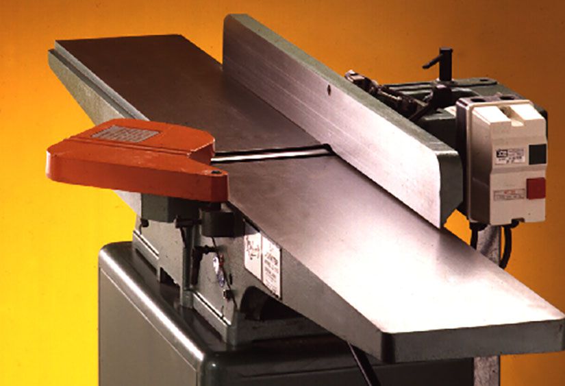
How your jointer works
Think of a jointer as a motorized hand plane turned upside down. In place of the hand planeʼs sole, jointers have a pair of tables that support the stock as you pass it over a rapidly turning cutterhead.
Down below, an elevation wheel provides a means for adjusting the height of the infeed table, and many jointers have a control for the outfeed table as well. Machined dovetail ways align and guide the tables. You can fine-tune their alignment and lock them in place with accessible gib screws.
The cutterhead itself consists of a cylindrical assembly that typically holds two or three knives, each beveled like the blade on a hand plane. As shown below, the knives of a typical cutterhead are tightly wedged in place with gibs and gib bolts.

Five surefire tune-up tactics
To guarantee yourself a jointer that makes smooth and accurate cuts time after time, you need to align the infeed and outfeed tables, square up the fence, set the knives, and properly set the height of the outfeed table—in that order.
1 Check the tables for parallel alignment
Though the two tables arenʼt on the same plane during use, they must be absolutely parallel with each other along their entire length. Tables that sag at one end or the other (or both) will cause concave cuts. Tables that are high at their outer ends will produce convex cuts. And an outfeed table thatʼs parallel with the infeed table, but lower than the knives, will result in a condition called "snipe"—a small, hollow cut found at the end of a workpiece. This occurs when the infeed table no longer supports the workpiece.
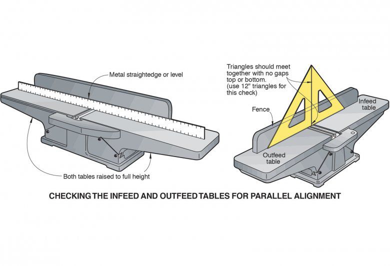
To align the tables, first unplug the jointer, slide the fence completely off the table, remove the cutterhead guard, and raise the infeed table to the same height as the outfeed table. Now, lay a level or straightedge across both tables as shown opposite page, top. If any light shows under the straightedge at the outer end of either table, the table is sagging. Usually you can correct this by tightening the upper gib screw (see drawing below).
If you see light under the straightedge in the middle, next to the cutterhead, the offending table or tables are high at their outer ends. Loosening the gib screws lowers them.
For even more accuracy when checking table alignment, use a pair of 12" triangles, as shown above right. Set one triangle on each table (not necessarily at the same height) with the 90° edges of the triangles touching. If you see a gap at the top, one or both tables are sagging at their outer ends. If thereʼs a gap at the bottom, one or both table ends are too high.
This method wonʼt tell you which table is the offender, but you can quickly find out by tightening the gib screws on the infeed table; if this doesnʼt bring them into alignment, try adjusting the outfeed table.
If your machine is old or gets lots of use, you may discover that tightening the gib screws wonʼt fix a sagging table. This happens because the dovetail ways have worn over the years and must be shimmed to compensate for the accumulated wear.
We prefer to shim the outfeed table, because its adjustment range is very small, but if your jointer has a fixed outfeed table, you have no choice but to work with the infeed side.
Shim with feeler gauges. To measure how much shimming is needed, loosen the lower gib screws, lift up on the outboard end of the table, and insert a feeler gauge 1⁄2 " onto the surface where the table contacts the lower casting as shown below. Release the table, snug the gib-adjustment screws, and check to see if the table is parallel with the other one. After youʼve found the right thickness of shims, cut 1⁄2 " lengths and install them. Finally, lock down the gib-adjustment screws and make a final check.

2 Square the fence for square cuts
A fence thatʼs not exactly 90° to the tables can cause you a truckload of grief. Even a slight angle error can multiply through the course of a woodworking proj-ect. Thatʼs why we like to precisely set the fence at the beginning of each work session.
With your drafting triangle, the job should take only a few minutes. Simply loosen the bevel lock, position the triangle as shown below, move the fence until you see no gaps at the table or fence, and retighten the lock. Use the same technique to set the 45° angle.

(At this point, you may decide to adjust your 90° and 45° stops—but donʼt rely on them for critical work such as edge joining. Instead, check with the triangle every time you change the angle of the fence.)
3 Set the knives
Even manufacturers have trouble setting knives perfectly. In our last test of 6" jointers ("Jointers Under $1,000," December 1995, pages 44–49), none of them arrived in their boxes with perfectly set knives. But guess what? All the machines still produced straight, smooth edges.
That said, weʼll show how to set your knives quickly and at least as accurately as the factory did. Aim for a maximum variance of .002–.003" between the knives. If you want to spend the better part of a Saturday at it, you can get them closer—but weʼd rather spend that time building projects.
If your machine came with a two- or three-legged knife-setting gauge, donʼt bother using it. These gauges are designed to set each knife exactly the same height above the surface of the cutterhead. But few jointers have cutterheads that are perfectly parallel with the tables, which means the cutterhead knives wonʼt be parallel with the tables either.
Weʼll provide you with three options for setting the knives—one low-tech and two high-tech. Which you choose depends partly on the type of cutterhead your machine has.
The first might be called the king of low-tech. It uses a simple wooden stick and a sheet of window glass. The stick should measure about 3⁄4 ×11⁄2 ×12" and have at least one flat surface. The glass should be cut to the width of the knives and about 12 inches long. To prevent cutting your hand, order polished edges.
Use the stick to determine the top of each knifeʼs cutting arc. Begin by drawing a mark all around the stick at about 1" from one end (known as "mark No. 1"). Then, follow Steps 1–4 in the drawings below. In Steps 1–3 mark No. 1 should be directly above the knife tip at all times. (It may help to keep light finger pressure on top of the stick.) After marking the cutterhead centerline on the fence, permanently scribe it with a scratch awl and triangle.

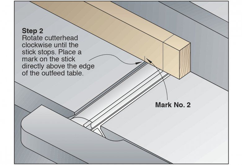


To set each knife, rotate the cutterhead until the cutting edge of the knife aligns with the mark on the fence. Check the alignment by setting a triangle against the fence and touching the knife. Immobilize the cutterhead by inserting tapered wood shims between the head and bearings, as shown below. Loosen the knife gib bolts just enough so that the knife moves with firm hand pressure. Raise the knife slightly higher than the top of the outfeed table. Now, lay the glass on the outfeed table, extended to fully contact the knife. Press the glass to the table and slowly snug up the gib bolts, starting with ones at the ends and alternately working toward the middle.

Take care that you donʼt overtighten the bolts. Too much torque can force a knife out of alignment. To limit the amount of pressure you can apply, turn the wrench with only your thumb and forefinger. Set each knife in turn, aligning it with the mark on the fence.
Now, use the stick to check that each knife is set the same height as the others. Lay the stick on the outfeed table, lining up any one of the three table edge marks, and rotate each knife past it. All should move the stick the same distance at both ends.
For a high-tech way to set jointer knives, invest in a setting tool such as the Magna-Set. It consists of two steel or plastic bars that slide along a pair of parallel rods. As shown below, each bar has small but powerful magnets that hold the jig to the table and the knives. This keeps each knife flush with the outfeed table while you tighten the gib bolts. Of course the Magna-Set wonʼt work with an aluminum outfeed table.

A dial indicator setup, such as the A-Line-It, offers yet another way to set the knives. (See the drawing below.) The indicator tells you exactly how high the knives are from end to end, and in relation to each other. These gauges work especially well with knives that you adjust with jack-screws that elevate the knives.

Finally, spin the pulley by hand to make sure the knives donʼt hit the tables or other parts. Reinstall the cutterhead guard, and plug in the machine.
4 Adjust the outfeed table
If your jointer has a fixed outfeed table, you can skip this step—and should use extra care and time setting the knives to ensure that the table and knife heights are the same. If you can move it, you need to adjust the outfeed table to exactly the same height as the tops of the knives.
Weʼve found that the easiest way to do this is to lower the table slightly, set the infeed table for a light cut, and slowly feed stock through the knives until the cut edge projects over the outfeed table about 1". Now, shut off the jointer, raise the outfeed table until it just contacts the workpiece, and lock it down.
To double-check this setting, finish jointing the edge and make a second pass, stopping to make sure the outfeed table fully supports the cut.
5 Test your adjustments
Now, itʼs time for a test drive. Select two pieces of stock that are approximately 3⁄4 ×4×36", and pass each over the cutterhead on the 3⁄4 " dimension. Use a shallow cut and keep pressure on the infeed side until 8" to 10" is supported by the outfeed table. Then, transfer pressure to the outfeed side.
After youʼve milled both boards, place the cut edges against each other. If any light shows through the joint, unplug the machine and recheck the alignment of the tables. If the alignment checks out okay, youʼre probably not feeding the stock properly.